
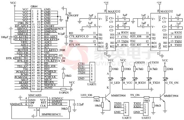
The working voltage Vcc of the module is 3.2 ~ 4.5 V, which can be provided by the step-down chip mic29302bu to reduce 5 V to the typical working voltage of 3.6 v. the five light-emitting diodes respectively indicate the GSM network registration status of the module, interact with GPRS network and the data receiving and transmitting status of communication serial port; Since the digital high level of the module pin is 2.75 V, the RS232 level conversion chip is best to use MAX3232, etc; The on / off pin and VREF are respectively provided to the terminal for controlling the hardware switching of the module and detecting the switching state of the module; USB port is the output port for debugging information and printing information.


 Official Wechat
 Tmall shop
 JD shop