
GPRS general packet radio service is a set of wireless transmission mode developed by using the concept of packet switching. GPRS network is based on the existing GSM (global mobile communication system) network. Some nodes need to be added to the existing GSM network, such as GGSN (GPRS gateway support node) and SGSN (GPRS service support node). The main function of SGSN is to record the current location information of the mobile terminal and complete the transmission and reception of mobile packet data between the mobile terminal and GGSN. GGSN mainly acts as a gateway and can be connected with a variety of different data networks, such as ISDN (Integrated Services Digital Network), PSPDN (packet switched public data network) and LAN (local area network). GGSN can convert GPRS packet data packets in GSM network to protocol, so as to transmit these packet data packets to remote TCP / IP or X.25 network.
GPRS network not only has the advantages of wide coverage, fast data transmission speed, high communication quality, always on-line and billing by flow, but also itself is a packet data network, supports TCP / IP protocol, and can directly communicate with the Internet without switching through PSTN (public telephone switching network) and other networks. Therefore, GPRS service has incomparable cost performance advantages in wireless internet access, environmental monitoring, traffic monitoring, mobile office and other industries.
1、 System design purpose
System design purpose: the client sends the data collected in the data collector to the GPRS data transmission terminal through RS232 serial port; The GPRS data transmission terminal converts the data into TCP / IP packets and sends them to the GPRS network, and then enters the Internet through service conversion; After the monitoring center obtains the TCP / IP packet of collected data from the Internet, it restores the TCP / IP packet of collected data into collected data through the program, so as to complete the whole communication from the collection site to the monitoring center through GPRS and Internet. The core design lies in the connection between MCU and GPRS module and the writing of communication software.
2、 Design of GPRS wireless data transmission system
1. System design scheme I
GPRS wireless data transmission system consists of client software, GPRS data transmission terminal, GPRS network and server software (as shown in Figure 1). The client software controls the sending and receiving of GPRS data transmission terminal through RS232 serial port, sends the collected data to GPRS network, and then enters the Internet network through service conversion. The server software receives the data uploaded through GPRS network, processes it and stores it in the database; The server-side software adopts Web page mode.
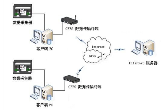
Figure 1 system structure diagram
The description of each part of the system is as follows:
(1) Client software. Send the collected data to GPRS data transmission terminal through serial port.
(2) GPRS data transmission terminal. Using the standard RS232 interface, the GPRS module can be controlled by the single chip microcomputer and the corresponding at command, and connected to the GPRS network.
(3) GPRS network. It supports TCP / IP protocol and can communicate directly with the Internet.
(4) Server side software. The server-side software adopts the host mode on the ordinary Internet; As a TCP server, it should have static public IP, open the listening port and can be accessed from the outside. It runs the TCP port listening program, receives TCP packets from GPRS client and sends response data to GPRS client.

The main task of server-side software is to receive, analyze and store communication data. First, the server starts the listening thread, listens to the TCP port, analyzes the obtained data packet after receiving the data packet, and then stores the analyzed data in the database (the program flow is shown in Figure 2). The server-side software shall have the following functions: ① monitor TCP port; ② Receiving data packets, analyzing data, storing data, and sending and receiving response frames; ③ Displays the received data.
Figure 2 main program flow chart of server software
2. System design scheme II
GPRS wireless data transmission system consists of five parts: client software, GPRS data transmission terminal, GPRS network, GPRS data receiving terminal and server software (as shown in Figure 3). The client software controls the sending and receiving of the GPRS data transmission terminal through the RS232 serial port, sends the collected data to the GPRS network, and then enters the Internet network through service conversion and transmits it to the GPRS data receiving terminal. The server software reads the data from the GPRS data receiving terminal, processes and stores it in the database.
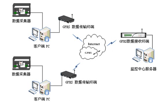
Figure 3 system structure diagram
The description of each part of the system is as follows:
(1) Client software. Send the collected data to GPRS data transmission terminal through serial port.
(2) GPRS data transmission terminal. Using the standard RS232 interface, the GPRS module can be controlled by the single chip microcomputer and the corresponding at command, and connected to the GPRS network.
(3) GPRS network. It supports TCP / IP protocol and can communicate directly with the Internet.
(4) GPRS data receiving terminal. The GPRS data receiving terminal corresponds to the GPRS data transmission terminal. When the collected data is uploaded by the GPRS data transmission terminal, the GPRS data receiving terminal receives the data uploaded by the GPRS data transmission terminal at the other end.
(5) Server side software. The server software adopts C / S mode; Receive data from GPRS data receiving terminal through serial port (program flow is shown in Figure 4). The server software shall have the following functions: ① serial communication; ② Data analysis and storage; ③ Displays the received data.
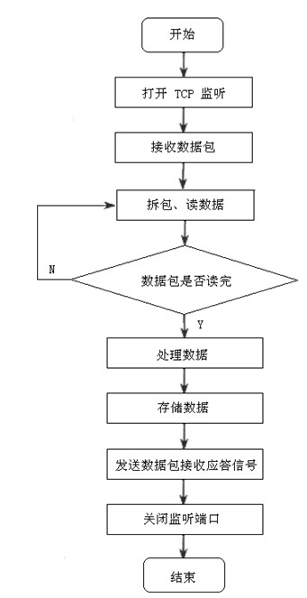
Figure 4 main program flow chart of server software
3、 Software design of GPRS communication system
The system software is written in C language and compiled in MPLAB environment. Because the system is a module of remote management terminal, we should abide by certain protocols in the programming, so as to ensure correct communication. The main body of the program is how to control the at command of GR47, initial setting of GR47 and processing of information data. Generally, the program can be divided into the following blocks: initial setting of GPRS connection, judgment and processing of short message, heartbeat processing without data transmission, data judgment and forwarding, etc. The main program is to organically combine these program blocks, control each other and cycle indefinitely.
2.1 establishment of connection
The implementation process of GPRS module connecting to Internet and GPRS network is as follows:
(1) MCU software controls the startup of GR47 module and waits for the normal startup of this module.
(2) Connect the GPRS module to the GPRS module through the serial port 47, and set up the corresponding connection to the network through the serial port 47.
2.1.1 basic settings
(1) GPRS ISP code.
At + iisp1 = * 99 * * * 1# / / nationwide
(2) Login user name.
At + iusrn = WAP / / GPRS network login
(3) Login password.
At + ipwd = WAP / / GPRS network login password
(4) Modem type.
At + imtyp = 2 / / define gprs modem
(5) Initialization command.
AT+IMIS=“AT+CGDCONT=1,ip,CMNET”
(6) Domain name server.
AT+IDNS1=211.136.18.171
//DNS server address, nationwide
(7) Extension code (XRC).
AT+IXRC=0
2.1.2 socket setting
(1) Establish a TCP communication.
AT+ISTCP:218.66.16.173,1024
Establish a socket connection. 218.66.16.173 is the IP address of the computer end of the application service center (the actual address is determined by the actual situation), and 1024 is the port number (the port number is determined by the setting of the central socket port listener). If the connection is successful, the lt8030 returns I / xxx. XXX is the handle number of this socket connection in lt8030. The central listener will display the IP address of the connected terminal. If the connection fails, the lt8030 returns I / error (xxx). XXX is the error code.
(2) Send data.
AT+ISSND%:xxx,:
Send data, XXX is the handle, the character length to be sent, and the data to be sent. After successful transmission, the data sent by the terminal can be seen at the central end. Data below 5K can be sent at most at one time.
(3) Query socket status.
AT+ISST:xxx
Query socket status, XXX is the handle. Lt8030 returns I /. If = 000, it indicates that the port is connected normally; If ≥ 1, the lt8030 receives the number of bytes stored in the buffer from the center through this port; If < 0, socket error.
(4) Receive data.
AT+ISRCV:xxx
XXX is the handle. The instruction will read the data stored in the buffer received by lt8030 from the center through the handle; Buffer can store up to 30K data.
(5) Close the socket channel.
AT+ISCLS:xxx
Close the socket channel and XXX is the handle.
2.2 data processing
The transmission of data packets in the data center server and GPRS server is based on IP packets, but it is not advisable to transmit IP packets in plaintext. Therefore, PPP (point-to-point protocol) is mostly used for transmission to realize the transparent transmission of data through GPRS module and Internet network. GR47 integrates TCP / IP protocol stack internally, so users do not need to write programs related to IP protocol, and can transfer data directly through GR47.
(1) Data transmission between the module and the PC on the Internet: the PC is required to have the IP address and open port of the public network and the operation software for monitoring the transmission message. In this way, when the module transmits data with the Internet, the message will be displayed. After the module is successfully connected to the network, as long as the MCU sends the data to GR47 through the serial port, GR47 will forward the data to the PC with the corresponding IP address.
(2) Processing of short message data: GR47 has the function of GSM and can send and receive short messages with mobile phones. The short message adopts PDU format. In the program, it is necessary to judge the arrival of the short message and read the content of the short message, and perform the corresponding functions according to the content. Finally, the result is constructed into PDU format and returned to the corresponding sender.
(3) GPRS communication heartbeat information: after the network connection is established, when there is no data communication within the set cycle, the GPRS module sends heartbeat information to the data service center, and the data service center responds to the response signal after receiving the heartbeat information.
(4) Storage of important data: in the program, some important common and changeable data, such as the IP address, port number, terminal address and SIM card number of the computer server, are stored in the EEPROM of the single chip microcomputer. Read out from EEPROM or re write data to EEPROM for setting when necessary.
2.3 main program flow
The main program flow is roughly as follows: first, initialize the MCU setting variables, which are generally 0; Initialize the corresponding configuration unit of MCU, such as setting port direction, setting interrupt priority, timer initialization, etc; Then, the single chip microcomputer controls the power supply of GR47 to decide whether to start it or not; After the startup is successful, query whether the network is registered successfully; After success, the connection between the module and PC server can be established, and data transmission and short message processing can be carried out; Send heartbeat information in a certain format as needed. (as shown in Figure 6)
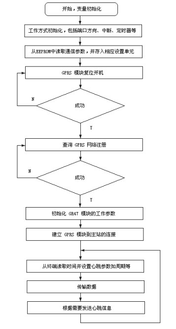
Figure 6 main program flow chart


 Official Wechat
 Tmall shop
 JD shop