
Abstract: This paper introduces the application of wireless SCADA technology in water plant, focuses on the solution of water well wireless radio monitoring in the wireless data transmission system of water plant based on PLC, and introduces in detail the process overview and system requirements of the whole project, as well as the structure of hardware and software of the system, The system hardware mainly adopts the all digital wireless data transmission radio of American MDS company and the programmable controller of Siemens company to build the wireless communication and data acquisition system, and the software adopts the point to multipoint half duplex communication mode.
As we all know, compared with traditional monitoring, wireless monitoring has the advantage of one-time investment and no operation cost. In many cases, users are often limited by geographical environment and work content, such as special geographical environment such as mountains, ports and open areas, which brings great inconvenience to wired network and wired transmission wiring engineering, The construction period of wired construction will be very long, or even impossible to achieve. At this time, the use of wireless network and wireless monitoring can get rid of the shackles of cables. It also has the advantages of short installation cycle, convenient maintenance, strong capacity expansion ability and rapid cost recovery.
The following takes a water plant as an example to introduce how to realize the radio monitoring of water wells in the water plant.
1、 Process Overview
The water plant introduced in this paper is a water plant with groundwater as the water source. The planned water supply pipeline is 36km, including 5km water transmission pipeline and 34km water distribution pipeline. The design water supply capacity of phase I project is 50000 tons / day. The plant has 10 water source wells, 1 surge tank and 1 water distribution plant. The motor capacity of submersible pumps in water source wells is 5 sets of 85KW, 4 sets of 45KW and the surge tank is 45KW. There are 1 water distribution pump room, 2 clean water tanks, 1 substation, 1 chlorination room and 1 Comprehensive Building in the water distribution plant. There are six 160kW water distribution pumps in the water distribution pump room, including two variable frequency speed regulating pumps and four power frequency pumps. The substation powered by two 10kV circuits includes two 10kV / o.4kv transformers with a capacity of 800kVA. There are three Chlorinators for chlorination. The water distribution pipe network is equipped with eight remote pressure measurement points.
2、 System requirements
(1) The control system is highly decentralized. The system needs to have the control ability of decentralized management, and each water distribution pump and water source well can start or stop control without affecting each other.
(2) It has the ability of centralized monitoring and unattended. The operator can centrally monitor the whole water plant in the central control room.
(3) The control system needs a miniaturized, low-cost controller with integrated SCADA communication function.
(4) The control system shall be able to adapt to the changes of environment and water supply and maintain stable water supply.
(5) Mainly logic control.
(6) It has reliability and safety.
(7) Ease of maintenance. The system shall have powerful alarm and fault self diagnosis functions to facilitate engineers to analyze and maintain system faults.
(8) Scalability. It is easy to expand the water plant and update the system in the future.
(9) Openness. The upper computer monitoring system is required to be open, and the monitoring system should be based on Microsoft's wind. Wsnt, 2000 or 9x platform, supports various standard protocols, such as OPC, 0dbc, ActiveX, DDE, etc.
3、 System structure
The system mainly solves the data collection and monitoring of each well in the central control room of the water plant. The whole system includes one master station and 20 slave stations. Among them, the master station is set in the central control room of the water plant, and the slave station is set at each water source well, pressure measuring point and pressure supplement point of the water distribution network. The master station and slave station use wireless communication for data transmission. This system is a typical point-to-multipoint star structure wireless communication system.
4、 Hardware structure
According to the characteristics of the water making process of the water plant and the functional requirements of the control system, and according to the specific situation of highly decentralized and centralized control and management of the plant, the system is constructed by using the all digital wireless data transmission radio of American MDS company
The main wireless communication equipment and data acquisition equipment adopt the programmable controller jy-rtu6640 of Juying electronics company. The system hardware structure is shown in Figure 1.
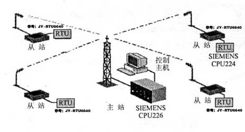
Figure 1 Schematic diagram of system hardware structure
5、 Software structure
The wireless communication SCADA system of the system adopts the point to multipoint half duplex communication mode, the master station PLC adopts the DFI half duplex master communication mode, other slave station PLC controllers adopt the DFI half duplex slave communication mode, and the master station PLC adopts the polling mode for each slave station and realizes the data exchange through the information (MSG) instruction. DFI master-slave communication mode can not only realize the communication between master station and slave station, but also realize the communication between slave station and slave station. The communication between master station and slave station can be based on information polling mode or standard polling mode. Next, take one master station controlling five slave stations as an example to program. part
The procedure is as follows:
(1) Master Program
Note: the master station adopts Siemens CPU 226 as the control host
Control the data reception and transmission of five slave stations in a round robin manner.
Main program:
LD SMO. 1 / / in the first scan cycle
Call initialize / / initialize
LD SM0. O
Call net / / free port communication
InitiaIize:
LD SM0. 0 / / this bit is always 1
Initialize:
LD SMO. / / this bit is always 0
MOVB 16#09 , SMB3 0
//9600b / s, 8-bit data, no verification, 1-bit stop bit
Movb 16#30, smb87 / / receive not allowed, timeout detection
MOVW +5,SMW90
MOVB 100,SMB94
MovB 16#AA,sMB89
ATCH RCVcomplete,23
ATCH XMTcomplete,9
...
...
LD SM0. 0
/ / send Mo 1290, VB 1290
MOVD &VB1201,VD1400
FOR VW1404,1,96
LD SM0. 0
XORB *VD1400,VB1298
INCD VD1400
NEXT
LD V1450. 0
LPS
R SM87. 7,1 / / not allowed to receive
RCV vb1000,0 / / refresh
EU
XMT vb1200,0 / / send
LRD
Ton t33,50 / / timing 500ms
LPP
A T33
R V1450. 0,1
S V1450. 1,1
LD V1450. one
S SM87. 7,1
Ton t34,50 / / timing 500ms
RCV vb1000,0 / / receive
A T34
R V1450. 1,1
...
...
XMT complete interrupt:
LD SM0. 0
S V1450. 1,1
R V1450. 0,1
(2) Slave program
Main program:
LD SMO. 1 / / in the first scan cycle
Call initialize / / initialize
LDN SMO. 7 / / if switching to term mode
EU
R SM30. O. 1 / / set to PPI Protocol
DTCH 23 / / various interrupts are prohibited
DTCH 9
DTCH 10
LD
SMo. 7 / / if switching to run mode
EU
S S M30. 0,1
ATCH RCVcomplete,23
//Receive the completion event and connect to the interrupt program o
ATCH XMTcomplete,9
//Send completion event to connect to interrupt program 1
Initialize:
...
...
LD SMO. O
XORB *VDl402。 VBl400
INCD VDl402
NEXT
LDB = vbl001, vbl20l / / compare the received address with the local address
B = vbl098, vbl400 / / the verification is correct
Athvbl002, vbl500, 96 / / decoding: asicc -- L6
MOVB 10,SMB34
Atch int-2, lo
CRETI
NOT
RCV VBlOOO,O
Xmtcomplete interrupt program:
D SMO. O
CV VBl000,0
Int-2 interrupt program:
...
...
6、 System installation, commissioning and operation
In this system, due to the long transmission distance, in order to reduce the system loss, the master station adopts 200MHz high gain omnidirectional antenna and domestic low loss cable as feeder, and each slave station uses 200MHz high gain directional antenna and domestic low loss feeder. Because there are many tall buildings around the water plant, in order to ensure the normal operation of the system, the wireless system was electrically tested on the spot before the implementation of the project, and the erection height of the antenna of the master and slave stations was determined according to the electrical measurement data.
7、 Conclusion
The installation, construction and commissioning of the project have been completed, and the system has been in safe operation for 5 years. The smooth implementation of the project has improved the automation level of the water supply system of the water plant and laid a solid foundation for the scientific and effective management of the water supply capacity of the water plant.


 Official Wechat
 Tmall shop
 JD shop